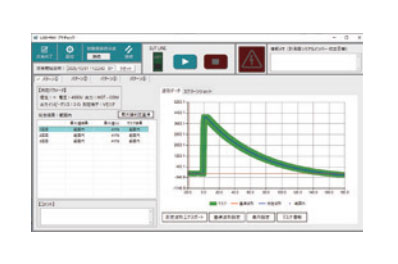


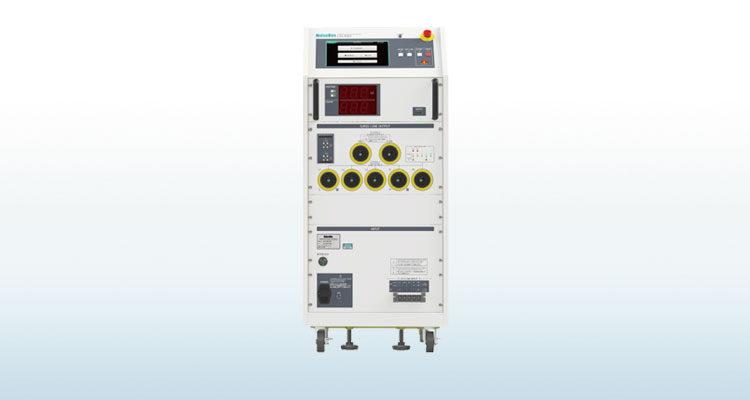
Lightning Surge Simulator LSS-FE01 Series
Shinyei Corporation of America is the sole authorized distributor of NoiseKen products. We offer the most direct sales of NoiseKen products available in the US.
Features
This simulator evaluates the immunity of electronic equipment by simulating "highenergy induced lightning noise" induced in power distribution lines and communication lines due to fluctuations in the earth's potential caused by lightning strikes. This is an entry model of the LSS-F03 series. (Maximum output voltage 6kV)
- Test equipment compliant with IEC 61000-4-5 Ed.3, IEC 61000-4-12 Ringwave standards.
- Maximum output voltage 6kV
- Large-screen operation panel with 10.1" LCD module for improved visibility and operability.
- Designed for smooth operation whether sitting or standing.
- Equipped with a display panel that allows the user to instantly grasp the test status (voltage and number of times applied) even from a distance.
- Uses a reliable output connector inherited from the LSS-F series.
- Connection cable settings are indicated by LED lamps.
- Can be combined with high-capacity external CDN (custom).
- PC software support allows for operation from a PC.
- Daily inspections can be easily performed using the pre-check software (optional).
Automated Malfunction Judgment Through PC Software
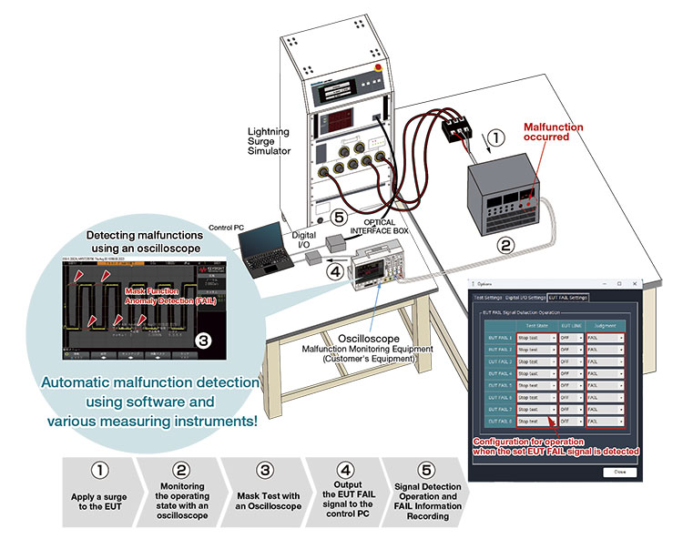
FAIL signals from oscilloscopes, image inspection systems, and other external devices can be automatically captured and recorded by the software. This eliminates the need for manual visual monitoring and ensures accurate recording of pass/fail results under each test condition.
Automatic judgment recording reduces operator workload while improving test reliability, repeatability, and efficiency.
With the optional National Instruments digital I/O module, the system can monitor and record up to 8 EUT FAIL signals simultaneously.
Specifications
Surge generator
| Parameter | Functions & Performance | Remarks | |
|---|---|---|---|
| 1.2/50μs-8/20μs Combination waveform |
Open circuit voltage | 0.5kV ~ 6.6kV ±10% | Cable length: 0.5 m (one side) Voltage step: 0.00kV-2.00kV: 0.01kV step 2.1kV-6.6kV: 0.1kV step Settings can be made from 0kV |
| Front time | 1.2μs±30% | ||
| Duration | 50μs±20% | ||
| Short-circuit current | 250A ~ 3300A ±10% | ||
| Front time | 8μs ±20% | ||
| Duration | 20μs ±20% | ||
| 0.5μs-100kHz Ring waveform |
Open circuit voltage | 0.25kV ~ 6.6kV ±10% | Cable length: 0.5 m (one side) Voltage step: 0.00kV-2.00kV: 0.01kV step 2.1kV-6.6kV: 0.1kV step Settings can be made from 0kV |
| Front time | 0.5μs±30% | ||
| Frequency | 100kHz±10% | ||
| Attenuation value | 2ndpeak:40% < 1st < 110% 3rdpeak:40% < 2nd < 80% 4thpeak:40% < 3rd < 80% |
||
| Short-circuit current | (Set voltage/12Ω) ±10 (Set voltage/30Ω) ±10 |
||
| Front time | 0.2μs ~ 1μs | ||
| Output polarity | Positive/Negative | ||
| Surge generation circuit type | Floating | ||
| Minimum charge time | 0.0kV-4.0kV: 5 sec. 4.1kV-6.6kV: 10 sec. |
1.2μs/50μs-8/20μs Combination waveform |
|
| 0.0kV-6.6kV: 5 sec. | Ring waveform | ||
AC/DC CDN
| Parameter | Functions & Performance | Remarks | |
|---|---|---|---|
| Superimposed surge waveform | 1.2/50μs-8/20μs combination waveform Ring waveform |
||
| 1.2/50μs-8/20μs Combination waveform |
Open circuit voltage | 0.5kV~6.6kV ±10% | Coupling circuit: 18μF Decoupling coil: 1.5mH Cable length: 0.5m on each side Setting is possible from 0kV Line input side open |
| Front time | 1.2μs±30% | ||
| Duration | 50μs+10μs /-10μs | ||
| Short-circuit current | 250A~3300A ±10% | ||
| Front time | 8μs±20% | ||
| Duration | 20μs±20% | ||
| Injection mode | Line-to-Line | Coupling circuit: 18 μF (10 Ω + 9 μF selectable) | |
| Between Line and PE | Coupling circuit: 10Ω + 9μF (18μF selectable) | ||
| Open circuit voltage | 0.5kV~6.6kV ±10% | Coupling circuit: 10Ω + 9μF Decoupling coil: 1.5mH Cable length: 0.5m on each side Setting is possible from 0kV Line input side open |
|
| Front time | 1.2μs±30% | ||
| Duration | 50μs+10μs /-25μs | ||
| Short-circuit current | 41.7A~550A ±10% | ||
| Front time | 2.5μs±30% | ||
| Duration | 25μs±30% | ||
| Injection mode | Line-to-Line | Coupling circuit (Line-to-Line): 18 μF (10 Ω + 9 μF selectable) | |
| Between Line and PE | Coupling circuit (Line-PE): 10Ω + 9μF (18μF selectable) | ||
| 0.5μs-100kHz Ring waveform |
Open circuit voltage | 0.25kV~6.6kV ±10% | Coupling circuit: 4.5 μF Decoupling coil: 1.5mH Cable length: 0.5m on each side Setting is possible from 0kV Line input side open (excluding simultaneous injection settings) |
| Front time | 0.5μs±30% | ||
| Frequency | 100kHz±10% | ||
| Attenuation value | 2ndpeak : 40% < 1st <110% |
||
| 3rdpeak:40% < 2nd < 80% | |||
| 4thpeak:40% < 3rd < 80% | |||
| Short-circuit current | (Set voltage / 12Ω) ±10 | ||
| Front time | 0.2μs~1μs | ||
| Injection mode | Line-to-Line Between Line and PE |
Coupling circuit: 4.5 μF (10Ω used in CW cannot be inserted) | |
| Simultaneous injection | Coupling circuit: 4.5 μF for each line | ||
| EUT power supply Line configuration | Single phase AC : L/N/PE DC:+/-/PE | Single-phase (A1/B1) type | |
| Three-phase AC : L1/L2/L3/N/PE (for both single and three phases)DC:+/-/PE | Three-phase (A3) type | ||
| EUT power supply Line power capacity | AC240V/20A MAX 50/60Hz DC125V/20A MAX |
Single-phase (A1/B1) type | |
| AC500V/50A MAX 50/60Hz DC125V/50A MAX |
Three-phase (A3) type | ||
| Decoupling coil | 1.5mH | ||
| Voltage drop | Less than 10% of rated voltage when rated current is applied | At the output terminal of the AC superimposed part*1 | |
| Residual voltage | 15% or less of injected surge voltage or power supply Less than twice the rated voltage (peak value) of the line |
||
| Phase angle control | 0°~ 360°±10° | EUT power supply 90V AC or more Operate at 50Hz / 60Hz ±10 |
|
Control Specifications
| Parameter | Functions & Performance | Remarks |
|---|---|---|
| Discharge interval | 5 sec - 999 sec (depending on the set voltage) | 1.2/50μs waveform |
| 5 sec - 999 sec (depending on the set voltage) | Ring waveform | |
| Discharge count | 1 to 999 times / 1 time step | |
| Trigger Input | Asynchronous | Depending on the repetition time |
| AC line sync 0° - 360° / 1° step | When AC superimposed | |
| Save Settings | Test settings can be named (title name) and saved in internal memory | |
| STANDARD mode | Preset settings regulated by the IEC61000-4-5 standard | Normal mode - common mode automatic transfer |
| Communication Function | RS-232 compliant optical communication |
Other specifications
- General Specifications
| Power supply | AC100V~AC240V ±10% 50Hz / 60Hz | |
|---|---|---|
| Operating environment | Temperature: 15 - 35° C Relative humidity: 25 - 75%. |
|
| Dimensions | W500 × H1140 × D600 mm | (excluding protrusions) |
| Weight | 135kg (A1), 155kg (A3), 135kg (B1) | |
- Safety Specifications
| Emergency Stop | Push-lock push button switch Test stop, High voltage OFF, EUT Line OFF |
EUT Line OFF is selectable |
|---|---|---|
| Interlock function | Surge output connector status detection, connector status detection for externally connected device | |
| Warning lamp display | LED blinks red when the test starts. | |
| Warning lamp connector | Equipped with a connector to connect a warning lamp. Warning lamp lights on at test start. | |
- Output monitor function
| Voltage Monitor | BNC output, 2000V/V Output accuracy: ±10% of the actual output ratio (±15% of the ratio of actual output in ring waveform) |
Surge out settings *2 When output is open No waveform guarantee |
|---|---|---|
| Current Monitor | BNC output, 1000A/V Output accuracy: ±10% of the actual output ratio (±15% of the ratio of actual output in ring waveform) |
Surge out settings *2 When output is short-circuit No waveform guarantee |
Model
| Model | Output waveform | CDN | Dimensions | Weight |
|---|---|---|---|---|
| LSS-FE01A1 | 1.2/50μs-8/20μs Combination waveform | AC Single phase / DC | W500 x D600 x H1140 [mm] |
130kg |
| LSS-FE01A3 | AC single-phase and three-phase/DC | 155kg | ||
| LSS-FE01B1 | 1.2/50μs-8/20μs Combination waveform 0.5μs -100kHz Ring waveform |
AC Single phase / DC | 135kg |
Standard accessories
| Name | Q-ty | Remarks |
|---|---|---|
| AC cable | 1 pc. | |
| Surge output cable | 2 pcs. | crocodile clip |
| Line output cable | 3 pcs. | Single phase (A1/B1) type |
| 5 pcs. | Three-phase (A3) type | |
| FG cable (2m) MODEL: 05-00070A | 1 pc. | M6 Round - M6 Round |
| Coaxial monitor cable (1m) MODEL: 02-00128A | 1 pc. | BNC−BNC |
| Interlock connector | 1 pc. | |
| Hi-voltage connector cap (MODEL: 05-00060A) | 5 pcs. | Single phase (A1/B1) type |
| 7 pcs. | Three-phase (A3) type | |
| Accessories bag | 1 pc. | |
| User's Manual | 1 copy |
ACCESSORIES
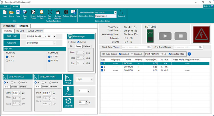
LSS-FE01 PC Software "RemoteW" MODEL:14-00075A
Dedicated software for PC remote control of the LSS-FE01 equipment. Total control of test conditions settings, program control, malfunction judgment and report generation is possible.
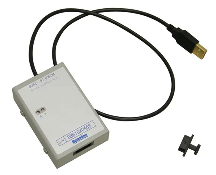
USB Optical Module Kit MODEL:07-00022A is required for communication between the LSS-FE01 and a PC.
USB Optical Module Kit MODEL : 07-00022A
Connection adapter used for remotely controlling the simulator from a PC.
Equipped with USB-Optical conversion fiber optic cable (5m).
Communication lines testing optional items
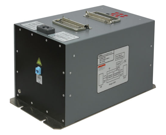
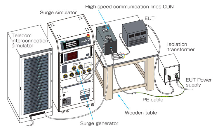
High-speed communication lines CDN MODEL:F-130814-1002 / F-130814-1004
This CDN product is used to apply surges to unshielded symmetrical high-speed communication lines with speed up to 000Mbit/s, as defined in the IEC 61000-4-5 Standard. Conversion cables (05-00147A) are required for the CDN connection to the LSS-FE01 simulator.
| Parameter | F-130814-1004-2 | F-130814-1004-4 |
|---|---|---|
| Maximum input voltage | 2kV | 4kV |
| EUT power capacity | DC65V 1A | |
| Maximum line Number | 8 lines | |
| EUT/AE connector | RJ-45 | |
| Dimensions | (W)400 × (H)230 × (D)240mm | |
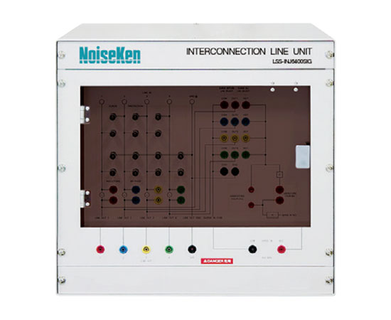
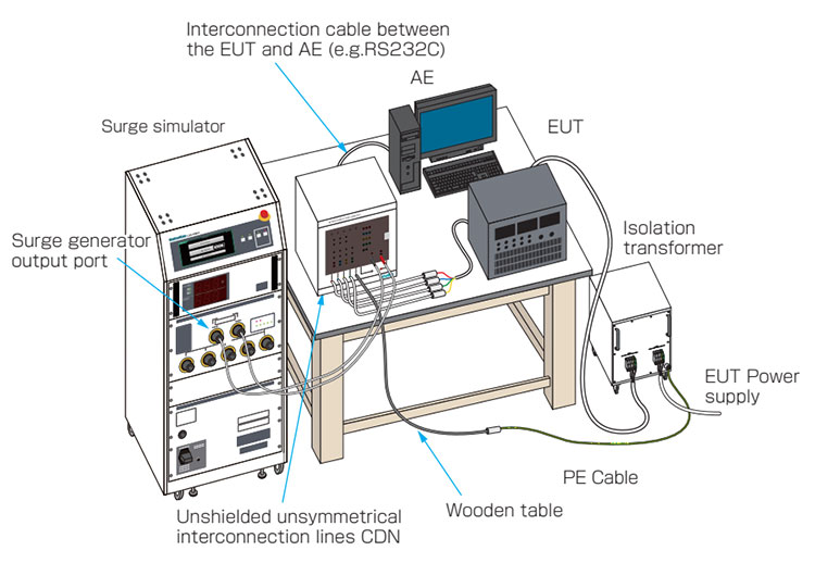
CDN for Interconnection Lines MODEL : LSS-INJ6401SIG
This CDN product is used to apply surges to interconnection lines as defined in the IEC61000-4-5 Standard. With The EUT power capacity of DC50V / 1A it is possible to inject surges to interconnection lines up to 6,600V. Possible to bypass inductor (20 mH) with connecting the attached connection plug to inductor bypass terminal in DC output. Possible to equip the attached surge protective arrestor between each line and ground.
Conversion cables (05-T1578) are required for the CDN connection to the LSS-FE01 simulator.
| Parameter | Specifications |
|---|---|
| Surge input voltage | 500V~6,600V (1.2/50μs-8/20μs Combination wave) |
| EUT power capacity | DC50V / 1A |
| Max. line number | 4 lines |
| Decoupling coil | 20mH each line |
| Matching resistor | 40Ω±10% |
| Dimensions / Weight | (W) 488 x (H) 456 x (D) 550mm Approx. 45kgs |
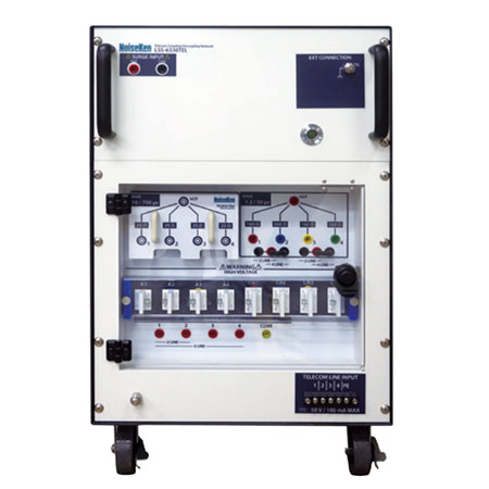
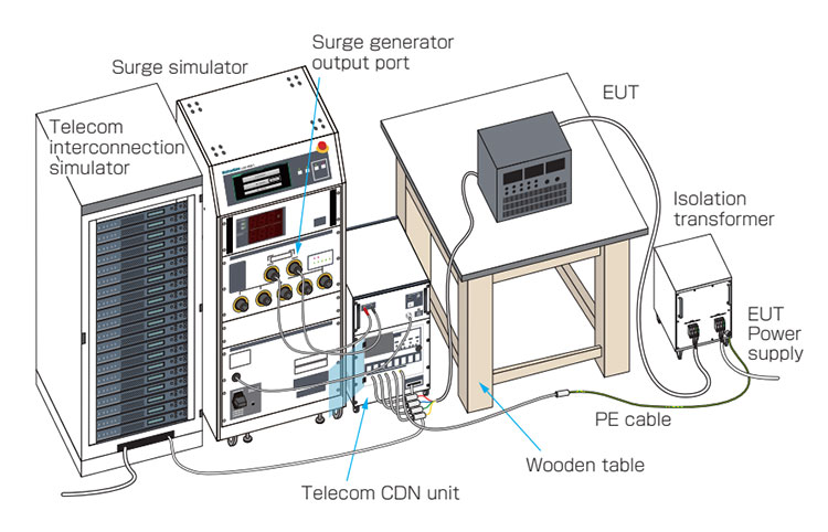
Telecom CDN unit (under development)
Perform surge testing applicable to unshielded symmetrical interconnection lines/communication lines as specified in the IEC61000-4-5 standard.
*A separate conversion cable is required to connect this device to the LSS-FE01.
| Parameter | Specifications | |
|---|---|---|
| Max superimposed surge voltage/current | 6kV/300A max | |
| Matching resistor | 40Ω±10% (1.2/50μs waveform) |
80Ω per line: at 2 lines 160Ω per line: at 4 lines |
| 1 line 25Ω (10/700μs waveform) | ||
| Line for EUT | 2 lines/4 lines | |
| DC50V/100mA MAX | ||
| Number of lines | 2 lines/4 lines | |
| Decoupling Coil | 20mH | |
Images and specifications are for reference only.
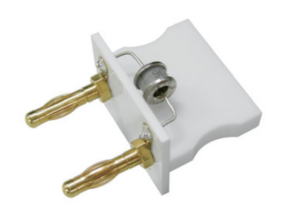
Arrester unit MODEL : 08-00012A
Arrester unit for surge decoupling.
Coupling arrester unit MODEL : 08-00016A
Arrester unit for surge coupling.
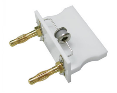
Power lines testing optional accessories
Isolation Transformer MODEL : TF-2302P, TF-6503P
Model TF-2302P is a single-phase isolation transformer rated AC240V/30A with dielectric strength of 4kV. Model TF-6503P is three-phase isolation transformers rated AC 600 V / 50 A and dielectric strength of 4 kV. For safety reasons, an isolation transformer is indispensable for AC powered testing for equipment.
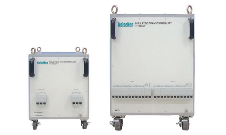
| MODEL | TF-2302P | TF-6503P |
|---|---|---|
| Maximum input voltage | Single phase AC240V Max (50/60Hz) | Single / Three phase AC 600 V Max (50/60 Hz) |
| Transformer wiring method | — | Star wiring |
| Maximum output current | 30A Max | 50 A Max |
| Dielectric strength | Primary winding to core AC4kV (1 minute) Secondary winding to core AC4kV (1 minute) Primary to secondary windings AC4kV (1 minute) |
|
| Insulation resistance | 100MΩ or more at DC500V | |
| Dimensions / Weight | (W)350×(H)475×(D)400mm (Except for eye bolt and handle) / approx. 60kg | (W)500×(H)640×(D)700mm (Eye bolts and handles excluded) / approx. 350kg |
| Accessories | ・AC single-phase input cable (5.5sq-3C 3m:Bar/None): 1pc. ・PE/FG cable (3.5sq 3m:R-terminals:φ6/φ6): 1pc. ・Instruction Manual: 1pc. ・AC single-phase output cable Model:05-00134A (3.5sq-3C 2m:Bar to R-terminal:φ5): 1pc. |
・AC 3-phase input cable (14sq-4C 3m:Bar/None): 1pc. ・PE cable (8sq 3m:R-terminal:φ6/None): 1pc. ・PE/FG cable (8sq 3m:R-terminals:φ6/φ6): 1pc. ・Instruction Manual: 1 pc. ・AC 3-phase output cable Model:05-00134A (14sq-4C 2m:Bar to R-terminal:φ5): 1pc. ・PE cable (8sq 2m:R-terminals:φ6/φ5):1 pc. |
Terminal Connection Board with Multi-Outlet(3P) MODEL : 18-00048B
A relay terminal board for connecting the output of the LSS-F03 series to the EUT.
By wiring to the included multi-outlet, you can directly connect a power plug that supports the standards of each country.
single phase 2 lines with PE (outlet withstand voltage 4.5kV )
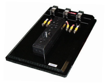
Terminal Connection Board with Multi-Outlet(5P) MODEL : 18-00058B
A relay terminal board for connecting the output of the LSS-F03 series to the EUT.
By wiring to the included multi-outlet, you can directly connect a power plug that supports the standards of each country.
three phase 4 lines ( outlet withstand voltage 4.5kV )
*The outlet is for single phase only.
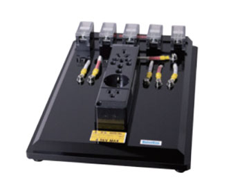
Terminal Block for 3P MODEL : 18-00047B
Terminal block board for CDN to connect EUT. 3 pins
Terminal Block for 5P MODEL : 18-00044A
Terminal block board for CDN to connect EUT. 5 pins
AC Line Input Cable (Single phase) MODEL : 05-00134A
Cable for connecting LSS-FE01 and isolation transformer(TF-2302P).*1
Bar terminal - Round terminal (Φ5) 3-wire 2m

AC line input cable (3-phase) MODEL : 05-00135A
Cable for connecting LSS-FE01 and isolation transformer (TF-6503P).
Bar terminal - Round terminal (Φ5) 3-wire 2m
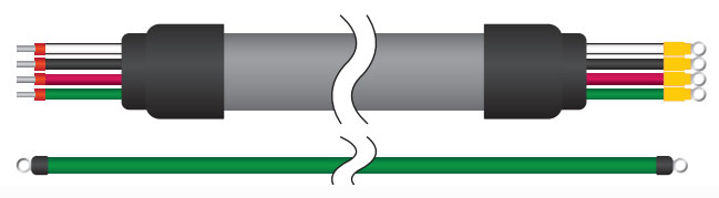
DC line input cable MODEL : 05-00136A
This cable connects the LSS-FE01 to a DC power supply and other devices.
Terminal Unprocessed - Round Terminal (Φ5) 3-wire 2m

Safety optional accessories
EUT Protective Safety Box MODEL : 11-00006A
Protection box to prevent access to EUT during the test. Further safety can be achieved by combining with the protective safety fence
(W) 600 × (D) 400 × (H) 350mm *protrusions excluded
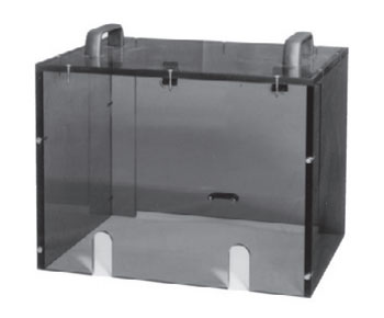
Protective Safety Fence MODEL : 11-00010A
Allows construction of a safe test environment by connecting with the lightning surge simulator's interlock function.
Combined use with the EUT protection box ensures a completely safe test environment.
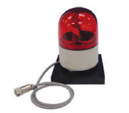
Warning Lamp MODEL : 11-00017A
Alarm lamp for LSS series. Allows to alert and call for attention by blinking during the test.
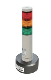
Tri-Color Pilot Light MODEL : 11-00015A
This indicator light is compatible with the LSS-FE01 series. During testing, the indicator light flashes to alert the user, and its three-color display changes according to the test status.
Calibration and inspection optional accessories
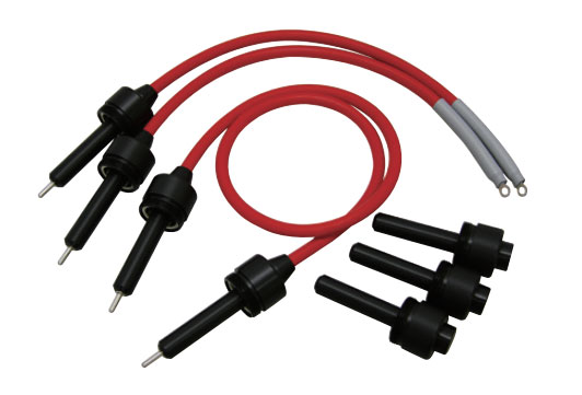
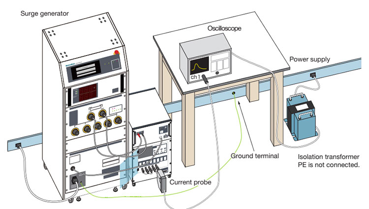
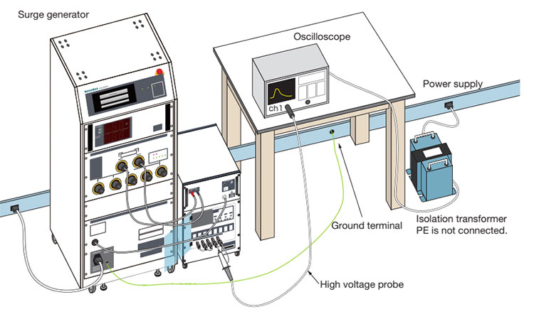
Waveform Checking Cables Set MODEL : 05-00099A
Jig for checking voltage waveforms and current waveforms of LSS-FE01 series.
Followings are necessary for the checking additionally.
- Oscilloscope (Differential operation function built-in)
- High voltage probes (for surge voltage measurement / Voltage resistibility necessary)
- Current probe (For surge short current measurement)
- Isolation transformer (for oscilloscope)
- Earth cable (for PE connection)
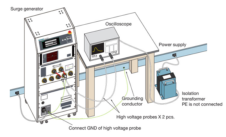
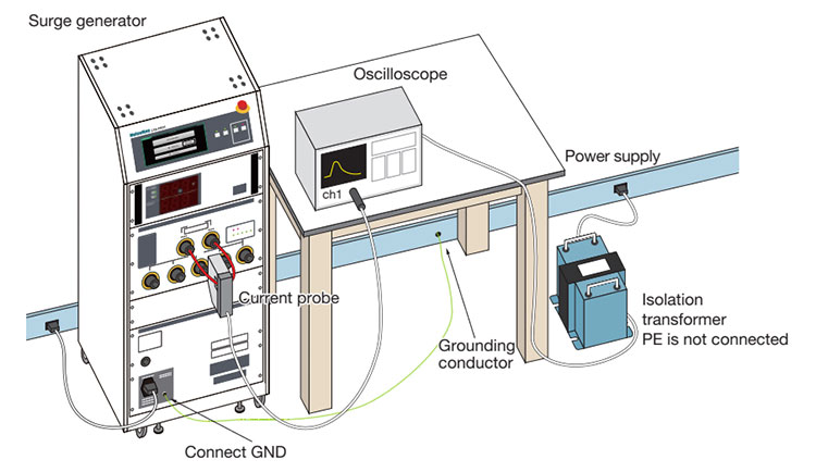
Surge Waveform Measurement (Setup of measurement from SURGE OUT with 05-00099A)
Telecom waveform check cable set MODEL : 05-00150A
Jig used for measuring the output waveform from the CDN for telecom line.
The following equipment is required additionally.
- Oscilloscope (with differential operation function)
- High voltage probe (when measuring surge voltage / withstand voltage required)
- Current probe (when measuring surge short-circuit current)
- Isolation transformer (for oscilloscope)
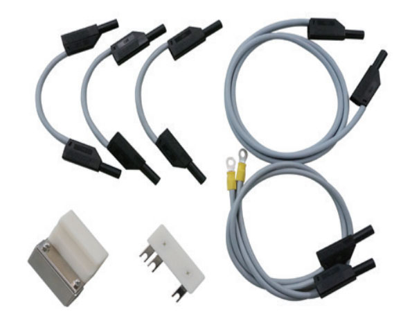
Measurement of surge waveform (example of measurement at telecom line CDN terminal with 05-00150A)
LSS-FE01 Pre-check Kit MODEL : 14-00076A
Pre-check kit (PC Software) for easy daily inspections of the LSS-FE01 Series.
Software, USB license key and a LAN cable are included.
This is not the measurement of compliance to the IEC 61000-4-5 standard.
*A separately sold oscilloscope (RIGOL MODEL:DS1202Z-E) is required.