



Lightning Surge Simulator LSS-F03 Series
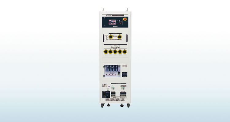
Shinyei Corporation of America is the sole authorized distributor of NoiseKen products. We offer the most direct sales of NoiseKen products available in the US.
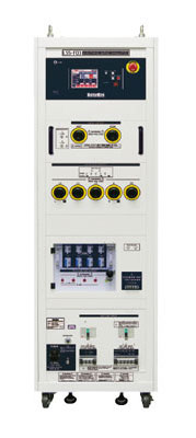
For a stricter test with a maximum voltage of 15 kV.
A tester simulatively generates "High energy induced lightning noise" which induced to distribution lines or communication lines by ground potential fluctuation caused by lightning strikes.
- Lightning surge simulator compliant with the IEC61000-4-5 Edition 3 requirements
- Maximum output voltage 15 kV (maximum coupling of 15 kV to AC / DC CDN and 6 kV to Telecom CDN) Enables to conduct the more extended reliability test including the destructive test
- Large size LCD for the operation is adopted for realizing better visibility and operatability
- Easy operation for the sequential tests with adoption of MPU control Surge output / Waveform switching / Polarity switching / Sequence can be automated sequentially
- Selectable either MANUAL or PROGRAM mode MANUAL mode is used for the test according to the Standard or performing single conditioned test and PROGRAM mode can perform different conditioned tests sequentially so that the tests can be performed easily along purposes.
- Excellent safety with equipment of interlock
- Standard equipment of terminal for checking the waveforms:Enable to check the waveforms in connection to an oscilloscope on hand with BNC cable
- Isolation transformers in line-up (Option)
- In order to avoid resonance with the power supply, possible to vary the constant of the decoupling network (1.5, 1.3, 1.0, 0.8 mH)(Customized production). When some products like a power conditioner for photovoltaic application are connected to a lightning surge simulator, the resonant phenomena may occur and the products may not work well. In LSS-F03 series (with customization), possible to change constants of the inductances so as to avoid such problem

Specifications
| Parameter | Specification | Note |
|---|---|---|
| Surge generating unit | ||
| 1.2/50μs - 8/20μs Combination waveforms | Output voltage 0.5 kV ~ 15 kV ± 10% | |
| Front time 1.2μs ± 30% | Common for all models Voltage step : 0.1 kV step The setting can be from 0 kV |
|
| Duration 50μs ± 20% | ||
| Output current 250 A ~ 7500 A ± 10% | ||
| Front time 8μs ± 20% | ||
| Duration 20μs ± 20% | ||
| 10/700μs-5/320μs Combination waveforms | Output voltage 0.5 kV ~ 15kV ± 10% | |
| Front time 10μs ± 30% | Models:C1A / C3A Voltage step : 0.1 kV step The setting can be from 0 kV |
|
| Duration 700μs ± 20% | ||
| Output current 12.5 A ~ 375 A ± 10% | ||
| Front time 5μs ± 20% | ||
| Duration 320μs ± 20% | ||
| Output polarity | Positive / Negative | |
| Interval | 10 sec. ~ 999 sec., depending on the set voltage | 10 sec. ( < 6 kV) 15 sec. ~ in 10/700μs waveform |
| Output impedance | 2 Ω ± 10% | 1.2/50μs waveform |
| 40 Ω ± 10% | 10/700μs waveform |
AC/DC CDN
| Coupling surge waveform | 1.2/50μs - 8/20μs combination waveforms | |
|---|---|---|
| Max. coupling surge voltage / current | Up to the values which can be set | |
| Coupling network Correspondent to IEC61000-4-5 |
18 μF | Between LINE - LINE (10 Ω + 9 μF selectable) |
| 10 Ω ± 9 μF | Between LINE - PE (18 μF selectable) | |
| Injection mode | Between LINE - LINE, Between LINE - PE | |
| Power supply lines structure for EUT | Single phase AC :L / N / PE DC :+ / - / PE |
Model : A1A / C1A |
| 3-phase AC :L1 / L2 / L3 / N / PE (Common for single phase and 3-phase) DC :+ / - / PE |
Model : A3A / C3A | |
| EUT power capacity | AC 240 V / 20 A MAX 50/60 Hz DC 125 V / 20 A MAX | Model : A1A / C1A |
| AC 500 V / 50 A MAX 50/60 Hz DC 125 V / 50 A MAX | Model : A3A / C3A | |
| Decoupling coil | 1.5 mH | |
| Phase angle control | 0 ~ 360° ± 10° |
CDN for Telecom lines (Only in models C1 and C3)
| Coupling surge waveform | 1.2/50μs - 8/20μs combination waveforms | ||
|---|---|---|---|
| 10/700μs - 5/320μs combination waveforms | |||
| Max. coupling surge voltage / current | 6 kV(waveform guaranteed up to 2 kV for 1.2/50μs waveform and up to 4 kV for 10/700 waveform ) | ||
| Impedance matching resistors | 40 Ω |
80 Ω per 1 line at 2 lines | 1.2/50μs waveform |
| 160 Ω per 1 line at 4 lines | |||
| 25 Ω per line | 10/700μs waveform | ||
| Coupling mode | Common mode | ||
| Coupling network | Gas arrestor : 90 V | ||
| Line for EUT | 2 lines / 4 lines DC 50 V / 100 mA MAX | Selectable | |
| Decoupling coil | 20 mH | ||
OTHERS
| Voltage monitor | BNC output, 1 / 2000 ± 10% | In open-circuit for SURGE OUT |
|---|---|---|
| Current monitor | BNC output, 1 mV / A ± 10% | In short-circuit for SURGE OUT |
| External communication | RS-232C optical communication | |
| Power supply | AC 100 V ~ AC 240V ± 10% 50/60Hz | |
| Power Consumption | 400 VA | |
| Dimensions | (W)555 × (H)1450 × (D)790 mm (A1A / A3A), (W)555 × (H)1800 × (D)790 mm (C1A / C3A) |
Protrusions excluded (in all models) |
| Weight | A1A : approx. 290 kg A3A : approx. 300 kg C1A : approx. 325 kg C3A : approx. 340 kg |
Standard accessories
| Parameter | Specification / Function | Q'ty | Correspondent model |
|---|---|---|---|
| Surge output cable | HOT / COM | 2 pcs. | Common |
| Output cable to power supply lines | For single phase : L / N / PE | 3 pcs. | A1A / C1A |
| For 3-phase : L1 / L2 / L3 / N / PE | 5 pcs. | A3A / C3A | |
| External interlock connector | 5P plug (Short between #1 - #3) | 1 pc. | Common |
| Power supply cable | For AC 100 V, 3P equipped with G connector cable | 1 pc. | Common |
● Certain periodical inspection shall be recommended since consumable parts are contained in the products.In the test to 3-phase 5 lines (with PE) power supply lines, a message which alert the inspection per around 200 sets (in the test to single phase (with PE) power supply lines, it is done per around 800 sets).
(1 set in this case means that the test shall be done with 2 levels (eg. 0.5 kV and 1 kV) for the test series according to IEC 61000-4-5) * Exchange timing of the parts may differ depending on the operative conditions and environment. Please contact us for more details.
(1 set in this case means that the test shall be done with 2 levels (eg. 0.5 kV and 1 kV) for the test series according to IEC 61000-4-5) * Exchange timing of the parts may differ depending on the operative conditions and environment. Please contact us for more details.